Color Data Table
Color Space
Jonathen Wilks
A Brief Intro
In Color Space, I implemented a fully data-driven color system using Unreal Engine 5.4.4’s Data Table functionality. At the heart of this system is a custom CSV file (DT_ColorsEdit.csv) that I created to define every valid gameplay color. This table standardizes how color is handled throughout the game using consistent naming conventions, RGB vector values, and a unique slider-based identifier for HUD integration.
Each entry in the table includes:
Material Name: The name of the Material Instance used to visually represent the color.
Slider Code: A shorthand vector (e.g. (0, 1, 0) for full green) based on the RGB sliders in the HUD. These use 0.25 increments between 0.0 and 1.0.
Color Vector: The final RGB value (stored as a vector3) used to drive material appearance, logic checks, and effects.
These vectors align precisely with the HUD sliders and are used throughout the game to match player-selected colors with puzzle object requirements. This system helped eliminate hardcoding, reduce human error, and create scalable color logic that supports both gameplay mechanics and visual feedback.
Notably, I chose not to use exact 0.25 intervals for the final color vectors themselves. While the HUD operates in those increments, the material colors are perceptually adjusted to make hues more visually distinct. I discovered the need for this during early playtesting, where players often struggled to differentiate between certain color, particularly shades of red. Some brief research revealed the scientific reasoning behind this: human color perception isn’t uniform, and certain hues (such as red) are harder to distinguish due to how cone cells are distributed in the eye. These small adjustments help account for those perceptual differences, ensuring better clarity and reducing unnecessary puzzle frustration.
MaterialName | SliderCode | Color Vector |
|---|---|---|
M_ColorMatch | (X=0.0, Y=0.0, Z=0.0) | (X=0.0, Y=0.0, Z=0.0) |
MI_CM_R1 | (X=0.25, Y=0.0, Z=0.0) | (X=0.05, Y=0.0, Z=0.0) |
MI_CM_R2 | (X=0.50, Y=0.0, Z=0.0) | (X=0.15, Y=0.0, Z=0.0) |
MI_CM_R3 | (X=0.75, Y=0.0, Z=0.0) | (X=0.40, Y=0.0, Z=0.0) |
MI_CM_R4 | (X=1.0, Y=0.0, Z=0.0) | (X=1.0, Y=0.0, Z=0.0) |
MI_CM_G1 | (X=0.0, Y=0.25, Z=0.0) | (X=0.0, Y=0.05, Z=0.0) |
MI_CM_G2 | (X=0.0, Y=0.50, Z=0.0) | (X=0.0, Y=0.15, Z=0.0) |
MI_CM_G3 | (X=0.0, Y=0.75, Z=0.0) | (X=0.0, Y=0.4, Z=0.0) |
MI_CM_G4 | (X=0.0, Y=1.0, Z=0.0) | (X=0.0, Y=1.0, Z=0.0) |
MI_CM_B1 | (X=0.0, Y=0.0, Z=0.25) | (X=0.0, Y=0.0, Z=0.05) |
MI_CM_B2 | (X=0.0, Y=0.0, Z=0.50) | (X=0.0, Y=0.0, Z=0.15) |
MI_CM_B3 | (X=0.0, Y=0.0, Z=0.75) | (X=0.0, Y=0.0, Z=0.4) |
MI_CM_B4 | (X=0.0, Y=0.0, Z=1.0) | (X=0.0, Y=0.0, Z=1.0) |
MI_CM_Y1 | (X=0.25, Y=0.25, Z=0.0) | (X=0.15, Y=0.05, Z=0.0) |
MI_CM_Y2 | (X=0.50, Y=0.50, Z=0.0) | (X=0.25, Y=0.12, Z=0.0) |
MI_CM_Y3 | (X=0.75, Y=0.75, Z=0.0) | (X=0.75, Y=0.50, Z=0.0) |
MI_CM_Y4 | (X=1.0, Y=1.0, Z=0.0) | (X=1.0, Y=1.0, Z=0.0) |
MI_CM_C1 | (X=0.0, Y=0.25, Z=0.25) | (X=0.0, Y=0.05, Z=0.05) |
MI_CM_C2 | (X=0.0, Y=0.50, Z=0.50) | (X=0.0, Y=0.15, Z=0.15) |
MI_CM_C3 | (X=0.0, Y=0.75, Z=0.75) | (X=0.0, Y=0.4, Z=0.4) |
MI_CM_C4 | (X=0.0, Y=1.0, Z=1.0) | (X=0.0, Y=1.0, Z=1.0) |
MI_CM_M1 | (X=0.25, Y=0.0, Z=0.25) | (X=0.05, Y=0.0, Z=0.05) |
MI_CM_M2 | (X=0.50, Y=0.0, Z=0.50) | (X=0.15, Y=0.0, Z=0.15) |
MI_CM_M3 | (X=0.75, Y=0.0, Z=0.75) | (X=0.4, Y=0.0, Z=0.4) |
MI_CM_M4 | (X=1.0, Y=0.0, Z=1.0) | (X=1.0, Y=0.0, Z=1.0) |
MI_CM_N1 | (X=0.25, Y=0.25, Z=0.25) | (X=0.25, Y=0.25, Z=0.25) |
MI_CM_N2 | (X=0.50, Y=0.50, Z=0.50) | (X=0.50, Y=0.50, Z=0.50) |
MI_CM_N3 | (X=0.75, Y=0.75, Z=0.75) | (X=0.75, Y=0.75, Z=0.75) |
MI_CM_NW | (X=1.0, Y=1.0, Z=1.0) | (X=1.0, Y=1.0, Z=1.0) |
Game Instance
Color Space uses a custom Game Instance to manage most of the game’s temporary data. Two of the most important data structures stored here are the Slider Code Map and the Material Required Colors Map. These maps drive core gameplay logic, assigning the correct required color vector to puzzle objects and applying the player’s color throughout the game.
The data table is loaded at runtime and used to generate these two maps. To keep things modular, I split the logic into separate event graphs within the Game Instance.
The Slider Code Map setup starts by extracting all material names from the data table and storing them in an array. The array is then looped through to access both the Slider Code and Color Vector for each row. The Slider Code (which matches the HUD vector input) is stored as the key, and the associated color vector becomes the value.
The Material Required Colors Map follows a similar process. It loops through a list of material names, looks up the corresponding color vector in the data table, and stores the material name as the key for that vector.


Controlling the Player's Color
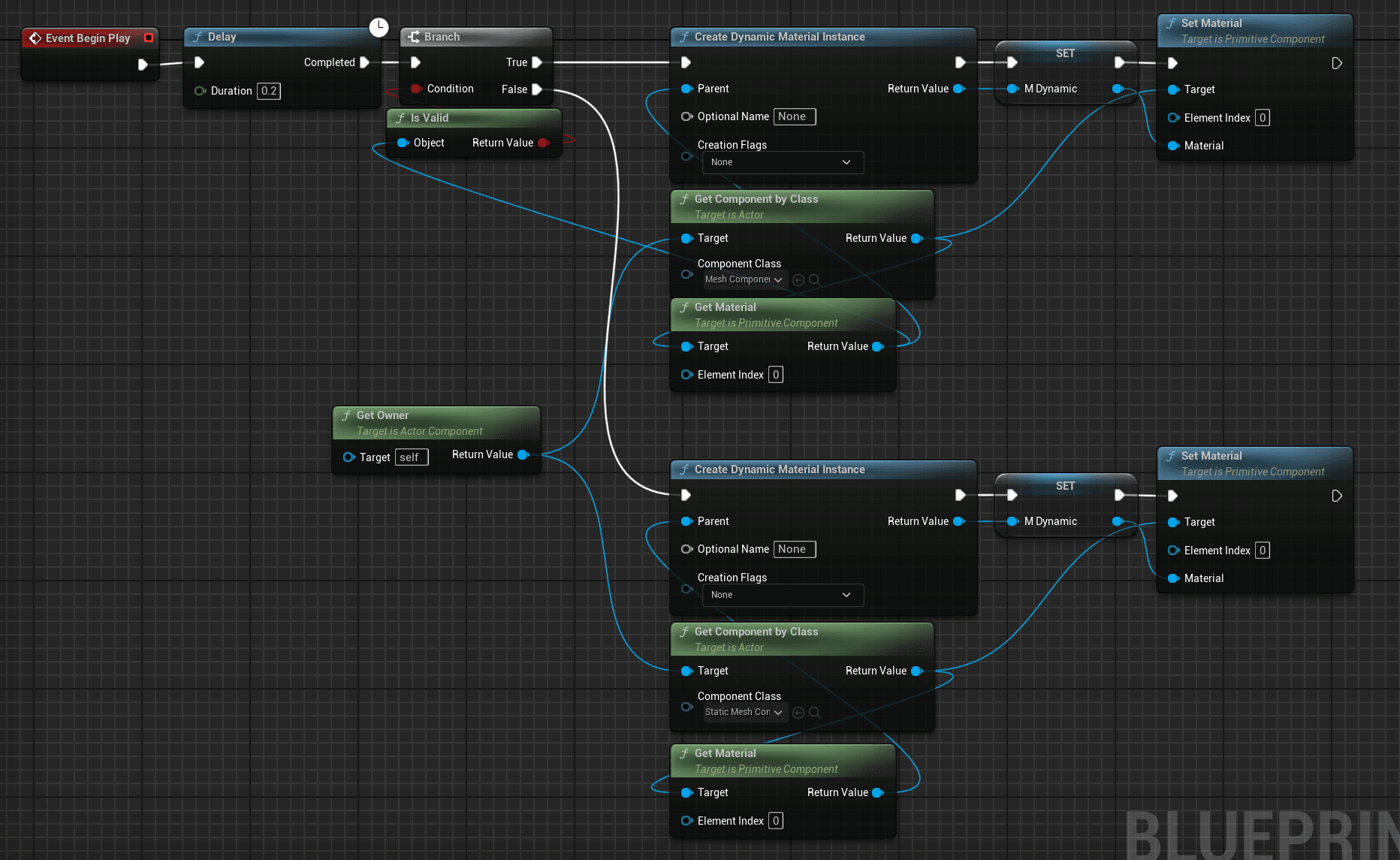
When the level begins, a dynamic material instance based on M_ColorMatch is created and applied to the player’s character mesh using an actor component blueprint.
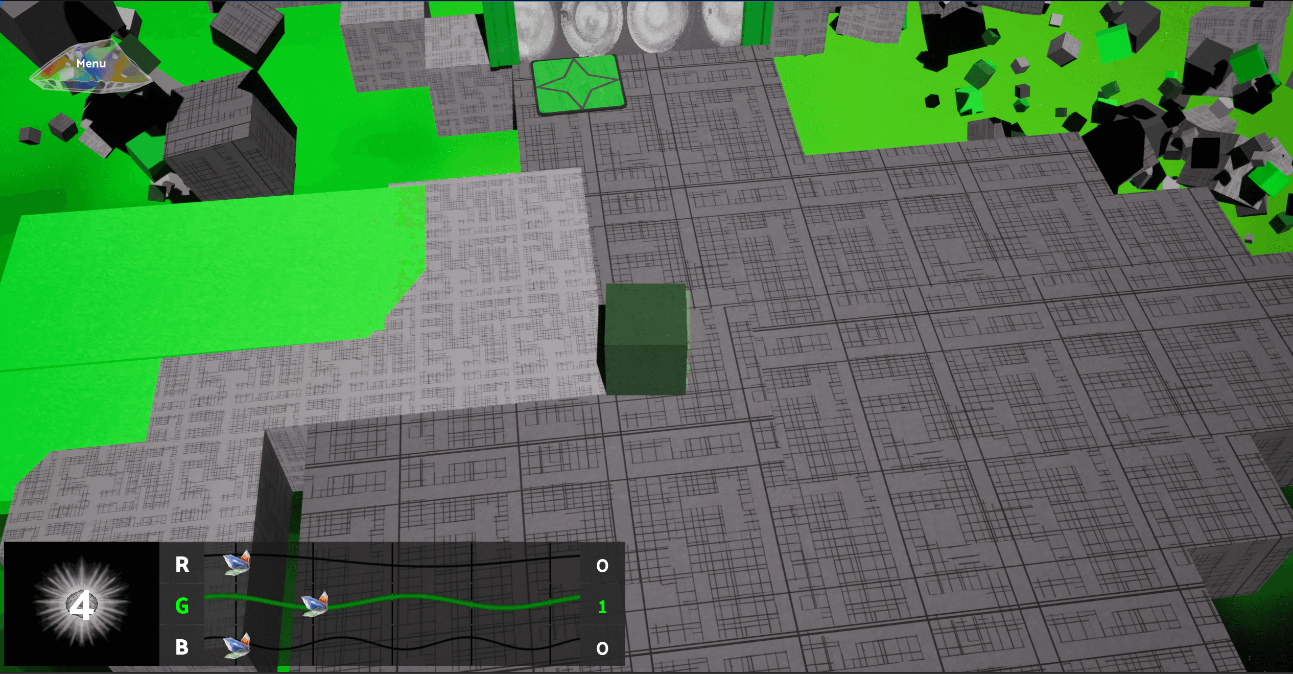
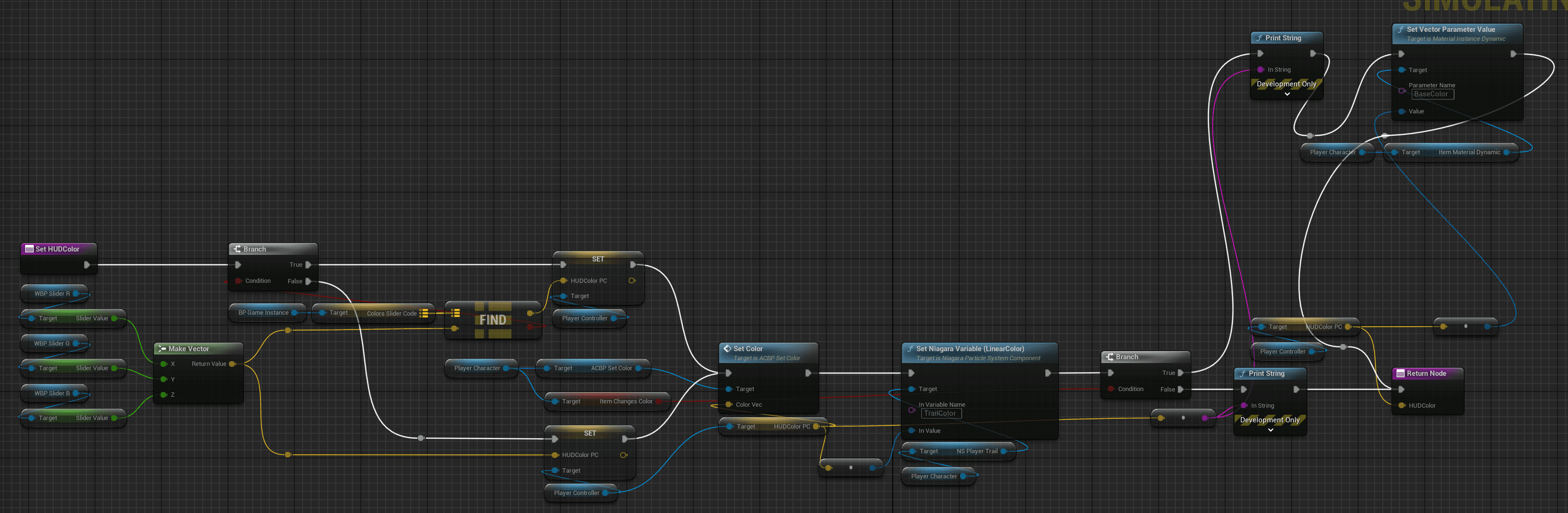
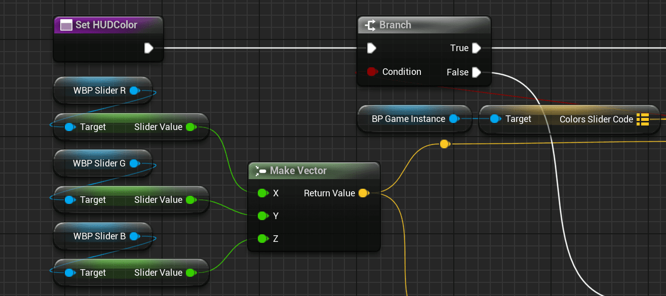
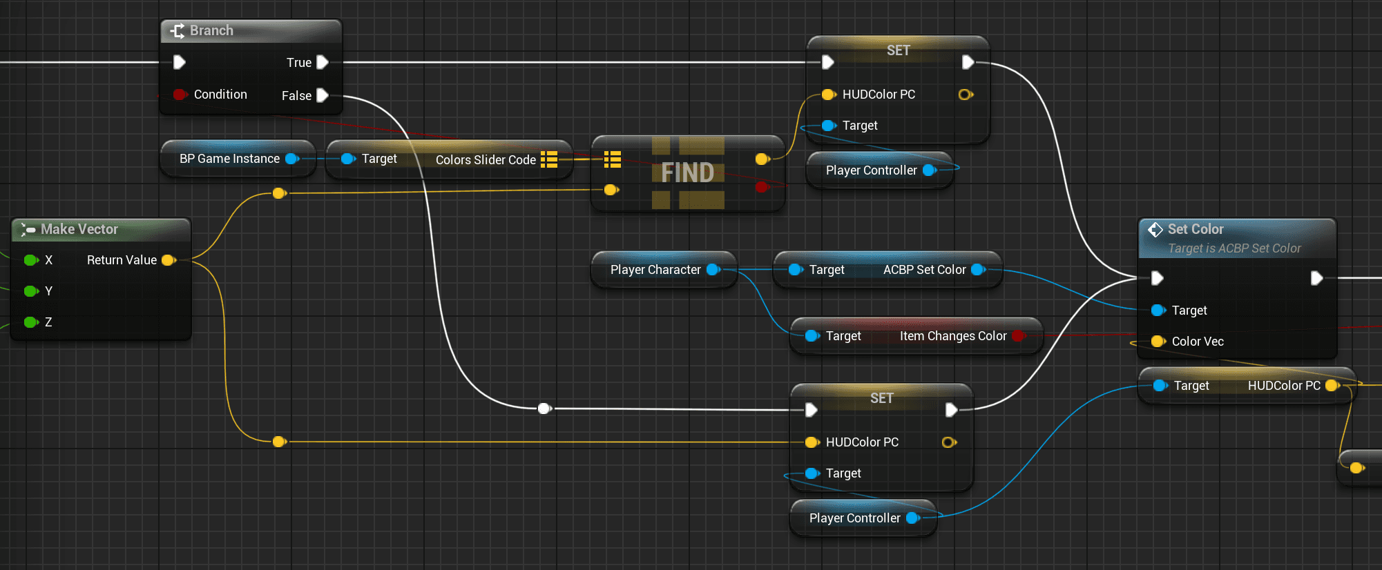
If the player has enough photons and has unlocked the required sliders, they can allocate those photons using RGB sliders in the HUD. Each slider’s value (a float between 0.0 and 1.0, in 0.25 increments) is combined into a vector3.
That vector is then used to check the Slider Code Map. If the vector matches an existing Slider Code, it retrieves a corresponding Color Vector (which may be slightly adjusted from the HUD value). If not found, the player’s color is set directly using the raw slider vector. While that color won’t match any puzzle objects, it adds a layer of experimentation and puzzle-solving.
The passed vector is converted into a linear color, assigned to the dynamic material's parameter, which creates the color change, and then sets the player's current color variable. Additionally, the color vector is also used set the color of the niagara trail particle effect that follows behind the player. This ensures the trail always matches the player's color.


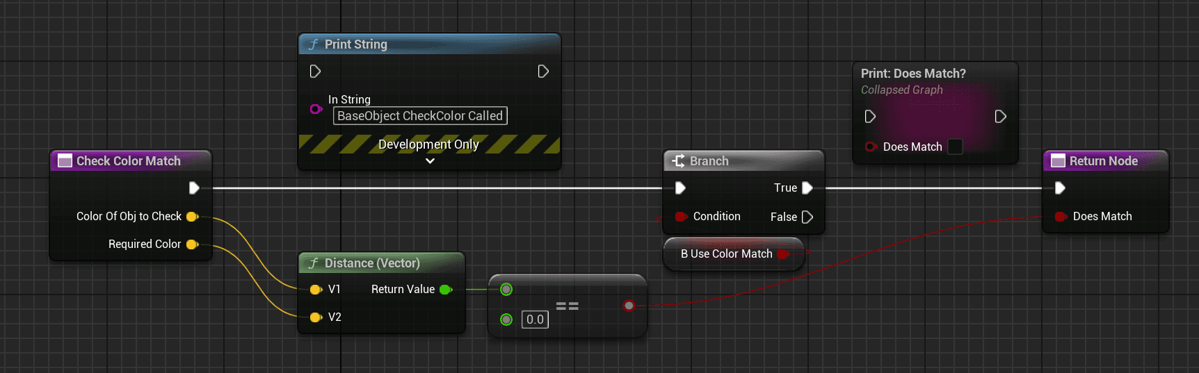
Assigning Required Color and Checking Colors
Each puzzle object in Color Space follows a parent-child blueprint architecture, which allows shared access to core logic functions. Once the Game Instance has initialized, each puzzle object reads the name of its assigned material and uses it to look up the corresponding color vector in the Material Map. This vector is then saved as the object’s Required Color.
This system was designed early in development before I transitioned to actor component blueprints, which I later used elsewhere for added modularity.
When a player, or another moveable puzzle object, interacts with a puzzle object, the Check Color function is called. The function compares the current color of the colliding object, such as the player, with the required color of the object being collided with and a distance check determines if the values are the same.